Linux + Launchpad Fail

I put the punchline in the title, so let me provide some justification and explanation. One of the things that initially excited me about the prospect of using the Launchpad was the presence of support on Linux. While not officially supported by TI, there is a project to add the msp430 family as a target for cross-platform gcc compilation. As an unsupported endeavor though, there exist some hiccups, both in compilation and communication with the launchpad under Linux.

On the surface, everything looks like it should be straight forward. Hack a Day has an article getting people started and while there is a bunch of compiling tools from scratch, the process is easy enough to follow. All the samples work as expected, but then you start coding and discover that nothing is so simple. I immediately noticed that the target processor you’re compiling for doesn’t match the chips included with the launchpad. Turns out that one of the limitations of the mspgcc project is that it lacks headers and support for every chip in the msp430 line. The project is aware of this shortcoming, but the product line is too expansive for them to maintain with the current system. Fortunately the MSP430G2231 (the more powerful of the two chips included with the launchpad) is functionally equivalent to the MSP430F2031 which has headers available. Simply changing around the header file linked gets past this bump in the road.

Next hurdle, compiler differences. A lot of MSP430 sample code relies on ics (ti’s compiler) specific compiler declarations and macros which GCC doesn’t replicate or emulate. For instance, this pattern

pragma vector=PORT1_VECTOR
__interrupt void PORT1_ISR(void)

is fairly common in the MSP430 literature and gcc doesn’t use the same syntax. Instead, you have to do something like

#include "signal.h"
.
.
interrupt (PORT1_VECTOR) PORT1_ISR(void)

It is important to note that these definitions (for the most part) are not part of the language specifications, so it is not that case that gcc isn’t a fully compliant compiler. Rather, compilers are free to implement their own directives at will so it is just the case that these are un-agreed to changes that TI made.

The community understands these differences, but they aren’t well documented in any central place. Instead of finding this information on the Launchpad wiki, I tracked it down by extensive googling on a thread in a launchpad discussion group. I was also pointed towards a simple perl program (you have to scroll down) someone wrote to convert code between CCS (TI’s compiler) and mspgcc. Using what I learned from these sources, I was able to successfully load all the demos I found online.

So now we can compile code examples intended to be run under Windows by changing the target processor and rewriting code. I’m ok so far – as a Linux user I’m used to things being possible but not necessarily easy. These relatively trivial issues I take as the cost of my OS choice. What pushed me over the line to doing this experimentation on a Windows computer was the instability of the serial connection.

One thing I got used to working with the Arduino was the ability to easily dump information via serial using

Serial.write(str)

Particularly since at the moment most of my exploration is testing sensor configurations, being able to watch the collected data live helpe. Having that communication channel available is also how I’ve been handling logging. Until I have a data storage and transfer system implemented, I’m reliant on having that communication channel. Which doesn’t work reliably on my linux system.

I’m not the first person to run into this issue, but have yet to find any sort of solution. I’ve found some posts that suggest flaky linux drivers or potentially bugs in the demo program. I’ve tinkered with it a bit, but haven’t had any luck getting it working. As a result, I’ll be doing my development on windows until I figure out a solution.

Now I’ve gotten some frustrations out of the way, it is time for some actual progress, so stay tuned for fun with solenoid water valves.
So that’s Embedded Programming…

Been a while, so let me catch up on what’s been going on. Mainly “real life” has been getting in the way of progress, but that’s not say nothing has happened.

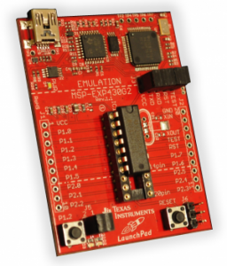
LaunchPadI made huge Digikey and Mouser orders to continue to build up my inventory and have the supplies needed to proceed. The process of putting those orders together and waiting for them to ship added to the delay. There were three categories of components I picked up. First, I bought a bunch of rf pieces to get started on learning wireless communication (more on this and my failures in a later post). I also bought a couple of Ti Launchpad MSP430 development boards and a bunch of components to control water valves. While I’m far from done learning my way around the MSP430, it has already been an interesting experience.

First, some motivation. Over time thinking about this project, I’ve come around to running nodes wirelessly instead of running wires around. The MSP430 ends up being a better choice than the Arduino (AVR) chips due to their extremely low power consumption. They also are highly cost competative – coming in at around a dollar a chip at retail. Even the development boards only cost $4.30. Of course, they’re also far more hardcore, a theme running through this whole project – why do something the easy way when you can do it the hardest way possible?

As soon as I started trying to learn to program the MSP430, I realized it was not quite at the same level as the work I’d done thus far on the Arduino. The arduino has a pretty high level wrapper to make it friendly for programmers new to embedded development, while the MSP430 has none of that prettiness. Instead, you have eight letter register names that you manipulate directly. I initially started they way I approach any new language – trying to do something and reading sample code as needed to fill in gaps in my knowledge. Unfortunately, while I know enough c to get started, the actual code and variables were completely foreign to me and it was clear I had to go deeper to understand what was going on.

Fortunately, TI has put together some really good tutorials to guide the new user through learning about the chip. Specifically the Getting Started Workshop does a really good job guiding you through what you need to get started. A great example of the difference between arduino and the msp430 is in the A/D conversion. On the arduino, you just call the function “analogRead.”

  sensorValue = analogRead(analogInPin);

On the MSP430, you have to do everything manually yourself – turn on the A/D converter, start the conversion, wait for the conversion to finish and then read out the result.

ADC10CTL1 = INCH_10 + ADC10DIV_0;                  // Temp Sensor ADC10CLK
ADC10CTL0 = SREF_1 + ADC10SHT_3 + REFON + ADC10ON;
_delay_cycles(5);                                  // Wait for Ref to settle
ADC10CTL0 |= ENC + ADC10SC;                        // Samp and convert start
P1OUT = 0x40;                                      // P1.6 on (green LED)
_delay_cycles(100);                                // Wait for conversion
ADC10CTL0 &= ~ENC;                                 // Disable ADC conversion
ADC10CTL0 &= ~(REFON + ADC10ON);                   // Ref and ADC10 off
tempRaw = ADC10MEM;                                // Read conversion value

I think it is pretty clear that just reading this code doesn’t help the newbie understand what is going on. You have to go into the processor documentation, but the workshop guides you through the process pretty well.

Having this level of control lets you have very precise control over power consumption. Having the A/D on increases the power consumption greatly, so you can adjust its availability to suit the needs of your specific project. The Workshop guides you through running operations with everything enabled and powered up, then through the guide adds additional power saving options culminating in having the CPU fall down to a super low power state. This is where the MSP430 line really shines – one guy ran one along with an LCD for a couple of weeks with only capacitors. This makes it really well suited towards being solar powered.

I’ve got a lot more learning to do which I’ll be sharing over the next couple of weeks + try to tie it back into the overall project. Clearly “growing with arduino” won’t work as a name for this project any more – I’ll have to figure something else out.

Soil Moisture Sensing 2

“Wait,” I hear you say, “didn’t you already bore us enough?” Well yes, but I haven’t come close to exhausting soil moisture sensing techniques. Lucky, lucky you…

Actually, I mainly forgot to cite my sources and give some handy links to more information! So rather than a thousand words on the many joys of capacitance sensing, here’s a link dump of some resources I found but didn’t mention last time.

  • SOWACS “Soil Water Content Sensors and Measurement” Yes, a whole website dedicated to sensing soil moisture. No, I have not set this to be my homepage (yet).
  • Wireless, Solar-Powered, Acoustic Wave Soil Moisture Detection System I’ll be real honest, this technique looks impractical to me – using an audio pulse to probe for moisture levels and using multiple emitters and detectors to cover the whole area. Then again, the technique isn’t very well documented compared to the hardware to implement it. I’ll be taking a look at this again.
  • Soil Moisture Circuit Nothing all that new here, but I want to point it out for using a shunt ammeter to boost the level to 0-5V.
  • Moisture Level thread on Parallax forums This has been a great resource for finding pages + resources, such as…
  • BodenFeuchte sensor In German (link is to google translated version of the page) – another capacitance based sensor, using a slightly different design and oscillator circuit. When I go to investigate capacitance testing, I hope to test this circuit out.
  • Wikipedia Moisture Sensors This is not a great page, I may be contributing to it. There is also Moisture Analysis which is more generic.

See, that wasn’t so bad?

Soil Moisture Sensing

I’m about to take of for a trip to Israel for work which, coming immediately after a visit by my parents has conspired to slow my progress. Today, I took a deep breath and started looking into moisture sensors in a serious way.

Currently, I have two probes running – the Vegetronix V400 and a resistive sensor of two galvanized nails shoved into the soil. While i’m collecting data and waiting to compare the output, my goal is to have a bunch of sensors placed around my garden and i’d like them to be homogeneous so I don’t have to worry about multiple sensor peculiarities. Time to dig into moisture sensing techniques and start evaluating options to scale my little sensing operation up.

Resistance Sensors

Most home build hobby sensors use the conductive properties of water to check for resistance changes. There are two basic types – those that probe the soil directly, essentially shoving two stakes in the ground, and those that use a different medium to check for moisture.

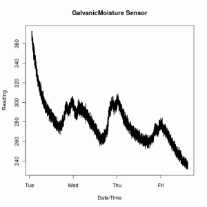
Galvanic Moisture Sensor ReadingsThe simplest option, of which I have one in the ground right now, is to test the resistivity of the soil directly by shoving two probes in the soil and measuring the resistance across them. Using two galvanized nails makes this incredibly cheap which is why they are quite so common among hobbyists. With the low cost comes a number of downsides. There is a high temperature dependency, so to be accurate in an outdoor environment requires adding a soil temperature probe. The chart to the right is the resistance across two approximately three inch galvanized nails spaced about an inch apart and you can clearly see a diurnal periodicity as the temperature changes. These sensors also suffer from soil composition and salinity dependencies – add fertilizer and your readings could be quite different. As they’re typically read using DC current, the probes do have a limited life span as electrolysis occurs. Typically, this effect is controlled for by only passing current through the probes at the time the reading is taken and simply replacing the probes yearly.

Cheap Vegetable Garderner is something of the granddaddy it seems of the type using a separate medium, in this case Plaster of Paris. Conceptually, the plaster absorbs water and dries out in concert with the soil it is buried in. Two conductive probes are embedded in the plaster and the resistivity between them is measured. While in principle, this controls for the soil composition, it adds its own problems. As explained over at GardenBot,

Initially when the plaster is dry, it has very high resistance (as you would expect). The problem is that plaster has an affinity for moisture, so as soon as the plaster comes in contact with any moisture at all, the sensor reading will drop to a very low resistance. And even if you completely saturate the sensor, you will not get the resistance to drop much lower than that.

With the problems in these types of sensors, essentially everywhere they’re used people just wave their hands and point out that for the application and given the cost they’re adequate. My project isn’t about being simply adequate, it is about learning and overkill otherwise I would have set up a simple timer and called it a day. So with that in mind, on we go to sensing capacitance!

Capacitance Sensors

Resistance isn’t the only electrical property to change with the addition of water into soil. The dielectric permittivity changes as well and can be probed in a number of ways, referred to in the literature as frequency domain sensing. Essentially, the dielectric of water is significantly higher than any of the other materials in the system causing the capacitance reading to be dominated by the water content.

Making this work requires a bit more circuitry than a simple resistance sensor which is why I think they aren’t commonly used in the DIY community. Mostly hints pop up in the occasional comment on one of the other methods. I believe this is actually the method employed by the Vegetronix v400, though they won’t say exactly the technique employed.

Fortunately, there is one well documented project that uses this technique. I’m not sure how exactly I found the link, but off of this page there is this paper titled “WiGreen Soil Moisture Monitoring System.” The project itself is pretty cool using mesh networking to have a sensor network reading soil moisture. Down on page 35, they go into detail of how they read the capacitance and then on page 48 are their circuit diagrams and PCB layout.

At this point, I’ve decided to try to construct my own capacitance sensor and have some design experimentation to be done. My current plan is to build the 555 circuit independent of the probe component so I can test different soil probe options – i.e. the coated spires mentioned in the comment or embed them in the pcb as in the WiGreen project. Expect more on this as I start experimenting.

I’m also not completely writing off a resistive approach. I’ll be putting a soil temperature sensor into the system soon and will use it to try to control for the temperature variation observed.

Sensors, check – Time for some valves…

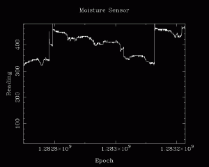
The moisture sensor works. Still some work to be done calibrating + tweaking signal levels to give it a wider range, but a swing from 350-450 (ish) is actionable. The first jump is where I discovered that I was using the wrong input voltage (5V instead of 3.3V). At the next leap, I watered then watched it decay over three days, watered again and watered near the very end.

Basically, this puts the moisture sensor at the same point as the temperature sensor – it is behaving correctly but still need some hardware tweaking to get the best possible accuracy + range.

I’m essentially building the system in blocks – bringing each piece to a basic level of operation before expanding into more grandiose plans. Right now, the sensors are working well enough on the breadboard, so I’m ready to bring more of the system on line. Next component – the water valves.

At the end of the day, all this system does is decide when to open water valves. My environmental inputs to that decision process are in place now to take care of the ‘action’ side of the equation. For now, I’m going to pick up two Orbit 62035 solenoid water valves and see what it will take to control them. From there, it will be a short hop, skip and a jump to a fully functional rudimentary system in place.

As with most of this project, I’m standing on the shoulders of those who have gone before. Ray has used a similar solenoid and posted schematics for it. The main component I’m going to have to acquire is the step up converter to give me 24V. Sounds like it is time for another SparkFun order!